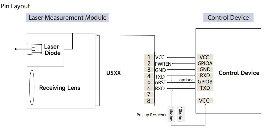
Distancia láser sensors with a TTL UART interface are widely used in robotics, automation, and embedded systems.
However, in real-world integration of LDL-S series TTL laser sensor de distancia modules, most issues do not come from wiring, but from misunderstanding the UART data frame format, distance parsing logic, and checksum mechanism.
This document serves as an official technical guide and protocol reference for LDL-S series TTL UART sensores láser de distancia.
All protocol descriptions, data formats, and code examples are based on the actual default UART output behavior of the LDL-S series, and are consistent with the official Arduino test logic supplied with the products.
What Is the TTL UART Protocol Used by the LDL-S Series?
LDL-S series laser distance sensors transmit measurement data using a TTL-level UART interface, enabling direct connection to microcontroladores such as Arduino, STM32, and other embedded platforms.
Default UART Parameters
- Logic level: TTL (3.3V or 5V, model-dependent)
- Baud rate: 115200 bps (default)
- Data format: 8 data bits, no parity, 1 stop bit (8N1)
- Flow control: None
- Output mode: Continuous output
From a system integration perspective, the UART physical layer is straightforward.
The critical part lies in understanding how measurement data is framed, encoded, and validated at the protocol level.
TTL UART Data Frame Structure (LDL-S Series)
The LDL-S series outputs distance measurements using a fixed-length binary UART data frame.
Fixed 9-Byte UART Frame Format
| Byte Index | Descripción |
|---|
| Byte 0 | Frame Header (0x59) |
| Byte 1 | Frame Header (0x59) |
| Byte 2 | Distance Low Byte |
| Byte 3 | Distance High Byte |
| Byte 4 | Status / Reserved |
| Byte 5 | Reserved |
| Byte 6 | Reserved |
| Byte 7 | Reserved |
| Byte 8 | Checksum |
Características principales:
- Frame header is always
0x59 0x59
- Frame length is always 9 bytes
- Distance data is transmitted in little-endian format
This fixed structure enables reliable parsing in continuous-output UART streams.
Distance Data Encoding
Distance values are transmitted as a 16-bit unsigned integer.
Distance Formula
Distance (mm) = (High_Byte << 8) | Low_Byte
- Unit: millimeters (mm)
- Byte order: little-endian (low byte first)
- No scaling factor is applied
Ejemplo
If the UART output frame contains:
0x59 0x59 0xFA 0x00 ...
Then the decoded distance is:
Distance = 0x00FA = 250 mm
The decoded value can be used directly without further conversion.
Checksum Calculation Method
The LDL-S series uses a simple 8-bit checksum to ensure data integrity.
Checksum Rule
Checksum = (Byte0 + Byte1 + ... + Byte7) & 0xFF
- Only the first 8 bytes are included
- The calculated value must match Byte 8
- No XOR or CRC algorithm is used
Checksum verification is mandatory for stable operation, especially in industrial or electrically noisy environments.
UART Output Behavior
By default, LDL-S series sensors operate in continuous output mode:
- Distance frames are transmitted automatically at a fixed update rate
- No external trigger or command is required
- The host MCU must continuously read and parse the UART data stream
A robust parsing process should always follow this order:
- Detect frame header
0x59 0x59
- Read a complete 9-byte frame
- Validate the checksum
- Decode the distance value
Arduino UART Parsing Example (Official-Compatible)
The following example matches the default UART output format of LDL-S series laser distance sensors and is consistent with the official Arduino test logic.
uint8_t buffer[9];void setup() {
  Serial.begin(115200);
}void loop() {
  if (Serial.available() >= 9) {
    Serial.readBytes(buffer, 9);    // Check frame header
    if (buffer[0] == 0x59 && buffer[1] == 0x59) {      // Calculate checksum
      uint8_t checksum = 0;
      for (int i = 0; i < 8; i++) {
        checksum += buffer[i];
      }      // Verify checksum
      if (checksum == buffer[8]) {
        uint16_t distance = buffer[2] | (buffer[3] << 8);        Serial.print("Distance: ");
        Serial.print(distancia);
        Serial.println(" mm");
      }
    }
  }
}
STM32 UART Parsing Example (HAL)
uint8_t rx[9];if (HAL_UART_Receive(&huart1, rx, 9, 100) == HAL_OK) {
  if (rx[0] == 0x59 && rx[1] == 0x59) {    uint8_t checksum = 0;
    for (int i = 0; i < 8; i++) {
      checksum += rx[i];
    }    if (checksum == rx[8]) {
      uint16_t distance = rx[2] | (rx[3] << 8);
      // Distance value is in millimeters
    }
  }
}
For production firmware, UART reception is typically implemented using interrupts or DMA for improved reliability.
Common Parsing Issues & Troubleshooting
| Edición | Likely Cause |
|---|
| Distance jumps randomly | Checksum not validated |
| Distance always zero | Incorrect byte order |
| Lecturas inestables | Frame misalignment |
| Unreadable data | Baud rate mismatch |
Debug recommendation:
During system bring-up, use a USB-to-TTL adapter to capture raw UART frames and verify the 9-byte structure before finalizing MCU firmware.
UART Protocol Reference Summary (LDL-S Series)
| Artículo | Especificación |
|---|
| Interfaz | TTL UART |
| Frame Length | 9 bytes (fixed) |
| Frame Header | 0x59 0x59 |
| Distance Bytes | Byte2 (Low), Byte3 (High) |
| Distance Unit | Millimeters (mm) |
| Byte Order | Little-endian |
| Checksum | 8-bit sum (Byte0–Byte7) |
| Output Mode | Continuo |


Protocol Applicability & Disclaimer
This protocol description applies only to LDL-S series TTL laser distance sensors operating in their default continuous output mode.
Please note:
- UART protocol details may vary across different sensor series or firmware versions
- This document does not apply to RS232, RS485, CAN, Ethernet, or ASCII-output sensors
- Customized firmware or command-based modes may use different data formats
Always refer to the official documentation supplied with the specific product when working outside default configurations.
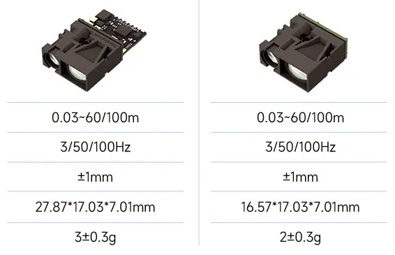
Different rangefinder modules explained in visual demonstrations
Integration Best Practices (Manufacturer Recommendations)
Based on practical integration experience with LDL-S series sensors:
- Always validate frame headers to prevent stream misalignment
- Never skip checksum verification in production systems
- Use interrupt or DMA-based UART reception for stable long-term operation
- Verify raw UART data first before implementing application-level logic
These practices significantly reduce integration risk and improve system reliability.
Summary
This document provides a complete and accurate description of the TTL UART protocol used by LDL-S series laser distance sensor modules, incluyendo:
- Fixed 9-byte UART data frame
- Little-endian distance encoding in millimeters
- Mandatory 8-bit checksum validation
- Official-compatible Arduino and STM32 parsing examples
Correct implementation of this protocol ensures stable distance measurements and reliable integration of LDL-S series laser distance sensors into embedded systems.
PREGUNTAS FRECUENTES
Can I directly connect the LDL-S sensor to an Arduino or STM32?
Yes.
The LDL-S series uses a TTL-level UART interface, which can be directly connected to:
Arduino boards
STM32 microcontrollers
Other embedded controllers with TTL UART ports
Please ensure:
Voltage level compatibility (3.3V or 5V, model-dependent)
Correct baud rate configuration (115200 bps by default)
No external protocol converter is required.
Does the LDL-S series require any trigger command to start measurement?
No.
By default, LDL-S series sensors operate in continuous output mode.
Distance data frames are transmitted automatically after power-up.
This makes the sensor easy to integrate for:
Control en tiempo real
Continuous distance feedback
Fast system bring-up and testing
What is the output unit of the distance data?
The distance value is output in millimeters (mm).
The decoded value from the UART frame can be used directly, without any scaling or unit conversion.
How do I know if a UART data frame is valid?
A valid LDL-S UART frame must meet all of the following conditions:
Frame header equals 0x59 0x59
Total frame length is exactly 9 bytes
Checksum matches the calculated 8-bit sum of Byte0–Byte7
If any of these checks fail, the frame should be discarded.
What happens if I ignore checksum validation?
Ignoring checksum validation may lead to:
Random distance jumps
Occasional incorrect readings
Unstable system behavior in noisy environments
For any production system, checksum validation is strongly recommended and should not be skipped.
Can I change the UART baud rate or output mode?
The default configuration is optimized for general integration.
If your application requires:
Different baud rates
Command-based output
Customized data formats
Please contact technical support before placing an order, as these options may require firmware customization.