Distance measurement is a fundamental requirement in many industrial automation systems, including positioning, level control, collision avoidance, and material handling. In PLC-based systems, Modbus distance sensors using RS485 communication are widely adopted due to their reliability, simplicity, and compatibility with industrial controllers.
This article explains how PLC distance measurement works using Modbus sensors and how to integrate them into typical industrial automation systems.
Why Use Modbus Sensors for PLC Distance Measurement
In Modbus distance sensors, RS485 serves as the physical communication layer, offering wide voltage tolerance and strong immunity to electrical noise.
With support for common-mode voltages from −7 V to +12 V, RS485 ensures stable data transmission in harsh industrial environments, making it a reliable choice for long-distance and multi-device sensor networks.
PLCs are designed for deterministic, stable control. Modbus RTU over RS485 aligns well with these requirements:
- Widely supported by mainstream PLC brands
- Simple register-based communication
- Strong resistance to electrical noise
- Capacité de communication à longue distance
Compared with analogique distance sensors, Modbus sensors provide numérique accuracy, better diagnostics, and easier multi-device integration.
For a broader overview of sensor selection and industrial considerations, see our Modbus laser distance sensor guide.
Typical PLC Distance Measurement Architecture
A standard PLC distance measurement setup includes:
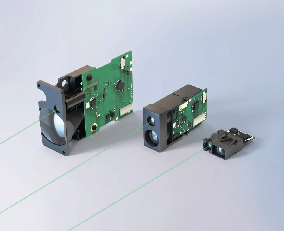
- Laser capteur de distance with RS485 Modbus RTU
- PLC with Modbus RTU master capability
- Shielded RS485 cable
- Termination resistors if required
- Optional HMI or SCADA system
The PLC periodically reads distance data from the sensor’s Modbus registers and uses it for control logic or monitoring.
RS485 Wiring for Modbus Distance Sensors
Correct wiring is essential for stable PLC communication.
Common RS485 Wiring Rules
- Use twisted-pair shielded cable
- Connect A+ to A+, B− to B− consistently
- Ground the cable shield at one point
- Avoid star topology for multi-drop networks
Improper wiring is one of the most common causes of unstable distance readings in PLC systems.
Modbus RTU Data Handling in PLCs
Most Modbus distance sensors store measurement values in holding registers.
Typical PLC workflow:
- Configure sensor address and baud rate
- Define Modbus holding register mapping
- Read distance value cyclically
- Apply scaling and filtering
- Use distance data in PLC logic
Because Modbus is standardized, no proprietary drivers are required, making commissioning faster.
Accuracy and Response Time Considerations
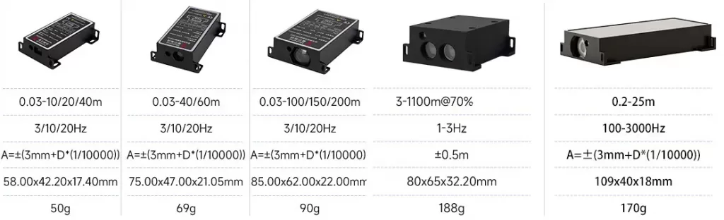
When using Modbus sensors for PLC distance measurement, engineers should consider:
- Capteur précision des mesures (±1 mm to ±3 mm typical)
- Update frequency (e.g. 10 Hz, 30 Hz, 100 Hz)
- PLC scan cycle time
- Vitesse de transmission de la communication
Matching sensor update speed with PLC scan time ensures stable and responsive control.
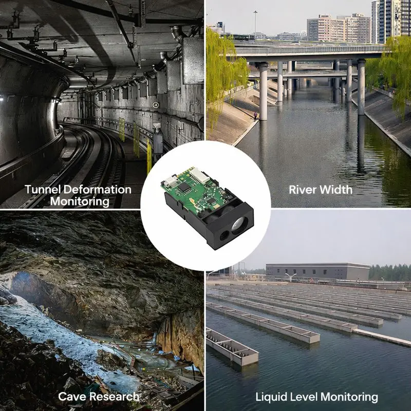
Industrial Applications of PLC Distance Measurement
PLC distance measurement using Modbus sensors is commonly applied in:
- Conveyor height and position monitoring
- AGV navigation and obstacle détection
- Crane positioning and anti-collision systems
- Tank and silo level measurement
- Automated warehouse systems
In these scenarios, industrial Modbus distance laser sensors provide reliable performance even in dusty, noisy, or vibration-prone environments.

Choosing the Right Modbus Distance Sensor for PLC Systems
Key selection factors include:
- Plage de mesure et précision
- RS485 Modbus RTU compatibility
- Environmental protection level (IP54 / IP67)
- Update frequency
- Installation method
A detailed comparison of industrial-grade options is available in our Modbus RTU laser distance sensor guide.
Conclusion
PLC distance measurement using Modbus sensors is a proven and widely adopted solution in industrial automation. By combining RS485 communication, standardized Modbus RTU protocol, and non-contact mesure laser, these sensors enable accurate and stable distance monitoring across diverse applications.
For system designers and integrators, understanding wiring, communication, and sensor selection is key to building reliable PLC-based distance measurement systems.
FAQ – PLC Distance Measurement Using Modbus Sensors
-
How does PLC distance measurement work using Modbus sensors?
PLC distance measurement using Modbus sensors works by reading distance values from Modbus RTU holding registers over an RS485 connection and using this data in PLC logic for monitoring or control.
-
Why are Modbus RTU sensors commonly used with PLCs?
Modbus RTU sensors are commonly used with PLCs because the protocol is simple, widely supported, stable in industrial environments, and easy to integrate without proprietary drivers.
-
Can PLCs read distance data directly from Modbus laser sensors?
Yes, PLCs can read distance data directly from Modbus capteurs laser by accessing holding registers via RS485, without the need for protocol converters or gateways.
-
What type of distance sensors are best for PLC systems?
-
What Modbus registers are used for distance measurement?
Distance measurement values are typically stored in Modbus holding registers, often as 16-bit or 32-bit integers representing distance in millimeters or scaled engineering units.
-
How accurate is PLC distance measurement using Modbus sensors?
PLC distance measurement using Modbus sensors typically achieves millimeter-level accuracy, commonly ranging from ±1 mm to ±3 mm depending on sensor type and measurement range.
-
How fast can PLCs read distance data from Modbus sensors?
The reading speed depends on the sensor update rate, Modbus baud rate, and PLC scan cycle, with typical systems achieving stable distance updates from 10 Hz to 100 Hz.
-
How many Modbus distance sensors can be connected to one PLC?
Up to 247 Modbus distance sensors can be connected to a single PLC on one RS485 bus, provided each sensor has a unique Modbus address and proper wiring is used.
-
What are common PLC applications for Modbus distance measurement?
Common PLC applications include conveyor positioning, AGV navigation, crane anti-collision systems, tank level measurement, and automated warehouse control.
-
Is RS485 wiring critical for PLC distance measurement stability?
Yes, proper RS485 wiring is critical because incorrect termination, grounding, or topology can cause communication errors and unstable distance readings in PLC systems.
-
Can Modbus distance sensors replace analog distance sensors in PLC systems?
In many cases, Modbus distance sensors can replace analog sensors by providing higher accuracy, digital stability, and better diagnostics without analog signal drift.
-
How do I choose the right Modbus distance sensor for a PLC project?
Choosing the right Modbus distance sensor depends on required measurement range, accuracy, update speed, RS485 compatibility, and environmental protection level.
-
Where can I find a detailed Modbus laser distance sensor selection guide?
-
What is the voltage range of RS485 used in Modbus sensors?
RS485 communication uses differential signaling, where data is transmitted through the voltage difference between two lines (A and B).
In industrial Modbus sensors, RS485 typically supports a wide common-mode voltage range from −7 V to +12 V, ensuring stable communication even in electrically noisy environments.
-
Why is RS485 suitable for industrial distance sensors?
RS485 is ideal for industrial distance sensors because it uses differential signaling with strong noise immunity.
Its wide voltage tolerance and resistance to electromagnetic interference allow reliable data transmission over long distances, even in factories with motors, inverters, and high-power equipment.