Correct wiring is critical to ensure stable communication and accurate measurements when integrating a laser range sensor TTL into embedded systems, robots, or industrial controllers. This guide explains TTL pinouts, voltage compatibility, power requirements, EMI protection, and practical troubleshooting tips—written for engineers, system integrators, and technical buyers.
1. Understanding TTL Wiring for Laser Range Sensors
대부분 laser range sensors with TTL output use UART 직렬 통신, making them easy to connect to:
- 마이크로컨트롤러 (MCU)
- Single-board computers
- Industrial gateway modules
- PLCs (via TTL–RS485 / TTL–RS232 converters)
Typical signal lines include:
| 핀 | 이름 | 설명 |
|---|
| VCC | 전원 | Sensor power input |
| GND | Ground | Common electrical ground |
| TX | Transmit | Sensor → MCU data |
| RX | Receive | MCU → Sensor commands |
⚠️ Always cross-connect TX ↔ RX between the sensor and controller.
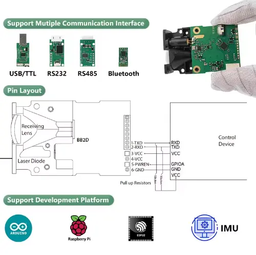

2. Laser Range Sensor TTL Pinout Explained
Standard 4-Pin TTL Interface
대부분 compact laser distance modules follow a 4-pin TTL pinout:
- VCC: Supplies power to the sensor
- GND: Must share ground with the host system
- TX: Serial data output from the sensor
- RX: Serial command input to the sensor
Some long-range or industrial variants may add:
- EN / PWM (enable or trigger)
- NC (not connected)
📌 Always confirm the exact pin order from the datasheet—pin sequence may vary between models.
3. Voltage Compatibility: 3.3V vs 5V TTL
One of the most common integration issues with a laser range sensor TTL is voltage mismatch.
Signal Logic Levels
| TTL Level | 일반적인 사용 사례 |
|---|
| 3.3V TTL | ARM MCUs, Raspberry Pi, ESP32 |
| 5V TTL | 아두이노 Uno, industrial MCU boards |
Best practices:
- If the sensor TX is 5V and MCU RX is 3.3V-only, use a logic level shifter
- If unsure, choose a sensor that supports wide voltage input (3.3–5V compatible)
⚠️ Never assume 5V tolerance—this is a common cause of permanent MCU damage.
4. Power Supply & Current Requirements
Laser range sensors draw more current than simple 디지털 센서.
Typical Power Specs
- Voltage: 3.3V / 5V / 12V (model-dependent)
- Average Current: 80–200 mA
- Peak Current: Can exceed 300 mA during measurement bursts
Power Wiring Tips
- Avoid powering directly from MCU I/O pins
- Use a dedicated DC rail or regulated supply
- Place decoupling capacitors near VCC and GND pins
Stable power directly impacts:
- 측정 정확도
- Communication reliability
- Sensor lifespan
5. EMI Protection & Long Cable Wiring
In real-world deployments, electromagnetic interference (EMI) is a major concern—especially in industrial or robotic environments.
Recommended EMI Countermeasures
- Use twisted-pair cables for TX/RX + GND
- Add shielded cables for runs over 30–50 cm
- Keep TTL lines away from:
- Motors
- High-current power lines
- Switching power supplies
For Long Distance Wiring (>1 m)
TTL is not designed for long cables. Consider:
- TTL → RS485 conversion
- Differential signaling
- Ground isolation modules
6. Common Wiring Mistakes & Quick Troubleshooting
No Data Output?
Checklist:
- TX/RX reversed
- Baud rate mismatch
- Incorrect voltage level
- Missing common ground
Unstable or Corrupted Data?
Likely causes:
- EMI noise
- Insufficient power current
- Long unshielded cables
Sensor Not Powering On?
Verify:
- VCC polarity
- Power supply current rating
- Inrush current during startup
7. Best Practices for Reliable TTL Integration
To ensure long-term stability when deploying a laser range sensor TTL:
- ✅ Match voltage logic levels
- ✅ Share a solid common ground
- ✅ Use short, shielded wiring
- ✅ Add surge and EMI protection
- ✅ Validate wiring before permanent installation
최종 생각
Correct wiring is the foundation of accurate distance measurement. By understanding TTL pinouts, voltage compatibility, power requirements, and EMI protection, you can avoid common integration failures and ensure reliable performance from your laser range sensor TTL in both prototyping and production systems.
If you are designing a custom system or evaluating sensors for industrial deployment, proper TTL wiring knowledge will save significant debugging time—and protect your hardware investment.
Laser Range Sensor TTL Wiring FAQ
What voltage does a laser range sensor TTL use?
Most laser range sensors with TTL output use 3.3V or 5V logic levels, depending on the model. Always confirm the logic voltage before wiring, as mismatched voltage levels can damage the controller or cause unstable communication.
How do I connect TX and RX on a TTL laser range sensor?
TX from the laser range sensor should be connected to the RX pin of the controller, and RX should be connected to TX. This cross-connection is required for UART communication.
Can I connect a 5V TTL laser sensor to a 3.3V MCU?
Only if the MCU input pins are 5V tolerant. Otherwise, a logic level shifter is required to safely convert the signal to 3.3V.
Why does my laser range sensor TTL show no data output?
Common causes include incorrect baud rate, reversed TX/RX wiring, missing common ground, or insufficient power supply current.
How long can TTL wiring be for a laser range sensor?
TTL signals are recommended for short cable lengths, typically under 50 cm. For longer distances, RS485 or differential signaling is recommended.