Why Embedded Laser Distance Sensors Matter
Endüstriyel Otomasyon için Modbus Lazer Mesafe Sensörü: RS485, RTU ve Model Seçim Kılavuzu
This article explains how an embedded laser mesafe sensörü can be integrated via UART communication, how different measurement and control modes work, and how multiple modules can be managed on a shared bus—based on real-world implementation experience with the LDL-S lazer mesafesi sensor from Meskernel.
What Is an Embedded Laser Distance Sensor?
An embedded lazer mesafe sensörü is a compact ranging module designed to be controlled directly by a host MCU or embedded processor. Instead of providing a standalone display, it communicates purely through dijital interfaces such as UART (TTL level), making it ideal for:
- Embedded control boards
- Robotik ve AGV systems
- Smart industrial devices
- OEM ölçüm modülleri
The LDL-S series is a typical embedded lazer mesafe sensörü module featuring millimeter-level accuracy, low power consumption, and a footprint of only 16.57 × 17.03 × 7.01 mm.
UART Communication Overview (TTL Level)
UART as the Preferred Interface
For embedded developers, UART remains one of the most practical communication protocols due to its simplicity and wide MCU support. The LDL-S uses TTL UART (3.3V) with the following characteristics:
- Baud hızı:
- Default: 115200 bps
- Configurable: 4800 – 115200 bps
- Frame format:
- 8 data bits, no parity, 1 stop bit
- Flow control: None
This makes the module compatible with common platforms such as STM32, ESP32, Raspberry Pi, and Arduino (via level matching if needed).
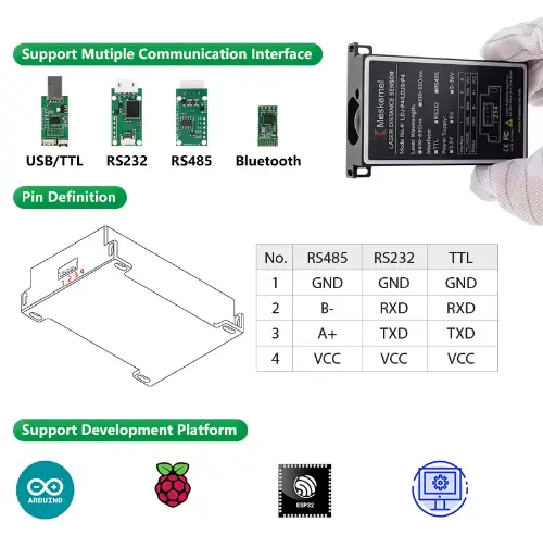
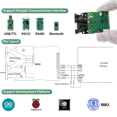
UART Wiring for Embedded Integration
A minimal embedded connection requires only five signals:
- VCC (3.5–4.2 V, recommended 4.0 V)
- GND
- TXD (module → MCU)
- RXD (MCU → module)
- PWREN (power enable control)
⚠️ Engineering note: The PWREN pin must be pulled high (≥2.0 V) to enable the module. This allows firmware-level power management, which is critical in battery-powered embedded systems.
This design makes the LDL-S a true engineer-friendly embedded distance measurement module.
Measurement Modes Explained (Single & Continuous)
Single Measurement Mode
Single-shot measurement is commonly used in event-triggered systems. After receiving a command, the sensor performs one ranging cycle and returns the result via UART.
Available single modes include:
- Automatic mode – sensor selects speed based on signal quality
- Low-speed mode – higher accuracy, longer measurement time
- High-speed mode – faster response, reduced accuracy
This flexibility allows developers to dynamically balance speed vs precision at runtime.
Continuous Measurement Mode
In continuous mode, the module repeatedly measures distance and streams data back at a fixed rate until stopped.
Supported continuous modes:
- Automatic continuous measurement
- Low-speed continuous measurement
- High-speed continuous measurement
To stop continuous measurement, the host simply sends 0x58 (‘X’ in ASCII)—a lightweight and reliable exit mechanism for embedded control loops.
High-Speed vs Low-Speed: How Engineers Should Choose
| Mod | Priority | Tipik Kullanım Örneği |
|---|
| Low-Speed | Doğruluk | Calibration, static measurement |
| Automatic | Balance | General embedded applications |
| High-Speed | Yanıt Süresi | Motion tracking, AGV obstacle tespit |
This makes the LDL-S suitable for both precision-oriented measurement systems and real-time embedded control.
Address Setting & Multi-Module UART Bus
Why Addressing Matters
In complex embedded systems, a single MCU often needs to control multiple sensors. The LDL-S supports addressable UART communication, allowing:
- Up to 8 modules per bus segment
- Up to 128 modules across multiple segments
Each module has a 7-bit address (0x00–0x7E), configurable via UART commands and stored in non-volatile memory.
Multi-Module Bus Architecture
All modules share TX/RX lines with pull-up resistors. The host polls modules by address, avoiding bus conflicts and enabling scalable sensor networks.
This design is ideal for:
- Multi-point distance monitoring
- Distributed measurement systems
- Embedded automation lines
Simple Control Timing
From an embedded firmware perspective, the control sequence is straightforward:
- MCU pulls PWREN high
- Module boots (~100 ms)
- Optional auto-baud handshake (0x55)
- Host sends measurement command
- Module returns distance + signal quality
- MCU processes data or triggers next cycle
This predictable timing makes integration easy even for real-time operating systems (RTOS).
Why This Embedded Laser Distance Sensor Is Engineer-Friendly
From an engineering standpoint, the LDL-S stands out because it offers:
- Compact mechanical design for embedded layouts
- Clear UART command structure
- Multiple speed and accuracy modes
- Addressable multi-module support
- Low standby and shutdown current
These features significantly reduce firmware complexity and hardware integration risk.
Typical Embedded Applications
This type of embedded lazer mesafe sensörü modülü is commonly used in:
- Robotik ve AGV navigasyonu
- Industrial automation feedback loops
- Smart storage and loji̇sti̇k systems
- Embedded inspection equipment
- OEM measurement subsystems


Sonuç
For engineers designing modern embedded systems, choosing the right distance measurement module is as much about communication and control as it is about accuracy. With UART-based control, flexible measurement modes, and scalable addressing, an embedded laser distance sensor like the LDL-S provides a robust foundation for precise and reliable mesafe ölçümü in compact designs.
If your project requires a small size distance measurement module that integrates cleanly into embedded firmware, UART-based lazer sensörleri are a proven and future-ready solution.
Frequently Asked Questions (FAQ) – Embedded Laser Distance Sensor Integration
What baud rate should I use when integrating an embedded laser distance sensor via UART?
By default, the embedded laser distance sensor operates at 115200 bps, which is suitable for most MCU-based systems.
If your module supports automatic baud rate detection, it can synchronize to common baud rates such as 9600, 19200, 38400, and 115200 bps using a simple handshake byte (0x55) after power-up.
Engineering tip:
If you are debugging early firmware or using long UART lines, starting with 9600 bps can improve stability.
Can this embedded laser distance sensor work directly with 3.3V microcontrollers?
Yes. The module uses TTL-level UART (3.3V logic) and is directly compatible with most modern MCUs such as STM32, ESP32, and Raspberry Pi.
However, note that:
Power supply voltage must be between 3.5V and 4.2V
Logic level (TX/RX) remains 3.3V
This separation allows easy integration in mixed-voltage embedded systems.
What is the difference between automatic, low-speed, and high-speed measurement modes?
Each mode optimizes a different performance parameter:
Automatic mode
The sensor dynamically balances speed and accuracy based on signal quality.
Low-speed mode
Prioritizes accuracy, suitable for calibration or static measurements.
High-speed mode
Prioritizes response time, ideal for motion detection or real-time control.
Engineers can switch modes dynamically via UART commands depending on system state.
Can I connect multiple laser distance sensor modules to one UART bus?
Yes. The embedded laser distance sensor supports addressable UART communication, allowing:
Up to 8 modules per bus segment
Up to 128 modules across multiple segments
Each module has a 7-bit configurable address (0x00–0x7E) stored in non-volatile memory.
This makes the module suitable for multi-point measurement systems without adding extra UART ports.
How is bus conflict avoided when multiple modules share TX/RX lines?
Bus conflicts are avoided by:
Assigning unique addresses to each module
Polling modules one at a time from the host
Using proper pull-up resistors on shared UART lines
The broadcast address (0x7F) can be used for synchronized measurement, but results must be read individually afterward.
What common mistakes cause UART communication failure?
Typical issues include:
TX/RX pins swapped
Incorrect baud rate configuration
Missing pull-up resistors (open-drain TX)
Insufficient power supply current
Forgetting to pull PWREN high
Most communication problems can be resolved by verifying wiring and checking UART settings with a logic analyzer.